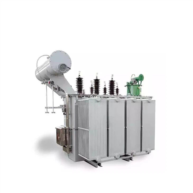
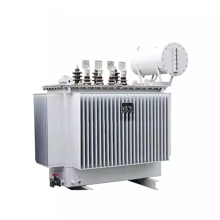
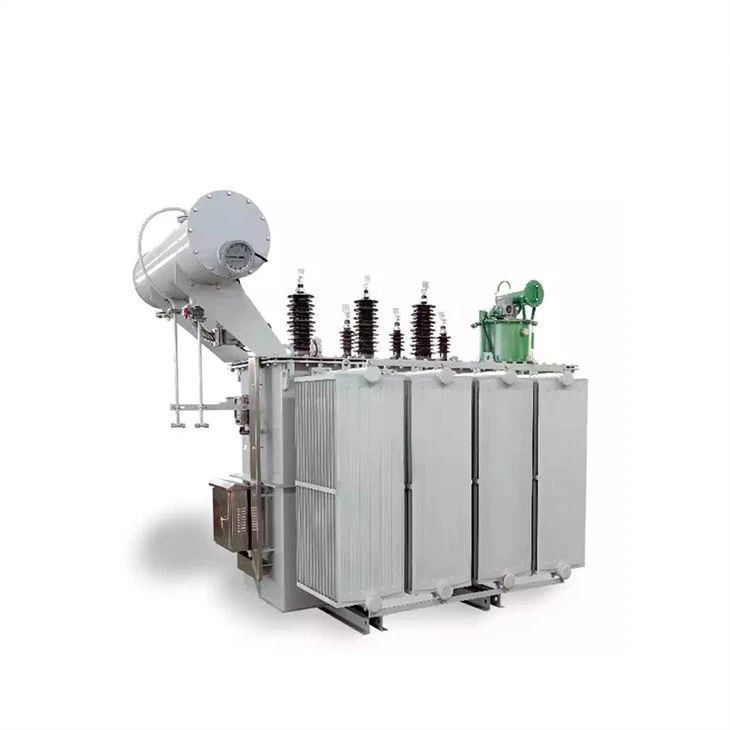
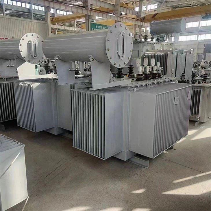
Oil Transformer
General introduction of Oil Transformer
Item:Oil Transformer
①Vacuum filter filling of transformer oil
②Stable electrical performance
③High dynamic stability
④Good thermal stability
⑤High overload capacity
⑥Long service life
- Introduction
- Contact Now
Oil transformers have stable electrical performance, strong overload capacity and no need to change oil during normal operation, which greatly reduces the maintenance cost of the transformer and extends the service life of the transformer.
Oil transformer is a structural type of transformer, i.e., the transformer's coils are immersed in oil. Oil-immersed transformers are generally installed in separate transformer rooms or outdoors due to the need for fire protection, and are characterized by large size, low cost, simple maintenance, good heat dissipation, high overload capacity, and wide adaptation to the environment.
Oil transformers are important components of substations and are generally installed in a separate transformer room. Relying on oil as the cooling medium, such as oil-immersed self-cooling, oil-immersed air-cooling, oil-immersed water-cooling and forced oil circulation, etc..
Generally, the main transformer of booster station is oil-immersed, the ratio is 20KV/500KV, 20KV/220KV, and the plant transformer used in general power plant to drive with its own load (such as coal mill, induced draft fan, fan, circulating water pump, etc.) is also oil-immersed transformer, its ratio is 20KV/6KV.

Model Description

S:Three phase
▢:"F" means air-cooled self-cooling without code
▢:"Z" means on-load voltage regulation without action,with magnetic load regulation and voltage regulation without code
▢:Performance level code
▢:Rated Capacity(kVA)
▢:Voltage class(kV)
Working Environment:
● Installation altitude: no more than 1000m above sea level
● Ambient temperature: -40℃~+40℃
Main Technical Parameters
■ 800KVA-31500KVA Three-phase double-winding non-excitation voltage regulating power transformer: | |||||||||
Model | Rated capacity (KVA) | Link group label | Voltage combination (KV) | No-load loss (W) | Load loss (W) | No-load current(%) | Short circuit impedance (%) | Tap range | Low pressure |
high pressure | |||||||||
S11-630 | 630 | Yd11 | 35 | ±5% | 3.15 6.3 10.5 | 830 | 7870 | 1.10 | 6.5 |
S11-800 | 800 | 980 | 9410 | 1.00 | |||||
S11-1000 | 1000 | 1150 | 11540 | 1.00 | |||||
S11-1250 | 1250 | 1410 | 13940 | 0.90 | |||||
S11-1600 | 1600 | 1700 | 16670 | 0.80 | |||||
S11-2000 | 2000 | 2180 | 18380 | 0.70 | |||||
S11-2500 | 2500 | 2560 | 19670 | 0.60 | |||||
S11-3150 | 3150 | 35 ~ 38.5 | ±5% | 3.15 6.3 10.5 | 3040 | 23090 | 0.56 | 7.0 | |
S11-4000 | 4000 | 3620 | 27360 | 0.56 | |||||
S11-5000 | 5000 | 4320 | 31380 | 0.48 | |||||
S11-6300 | 6300 | 5250 | 35060 | 0.48 | 7.5 | ||||
S11-8000 | 8000 | YNd11 | 35 ~ 38.5 | ± 5% | 3.15 3.3 6.3 6.6 10.5 11 | 7200 | 38500 | 0.42 | |
S11-10000 | 10000 | 8700 | 45300 | 0.42 | |||||
S11-12500 | 12500 | 10080 | 53900 | 0.40 | 8.0 | ||||
S11-16000 | 16000 | 12160 | 65800 | 0.40 | |||||
S11-20000 | 20000 | 14400 | 79500 | 0.40 | |||||
S11-25000 | 25000 | 17020 | 94100 | 0.32 | |||||
S11-31500 | 31500 | 20220 | 112900 | 0.32 | |||||
| Note 1: Transformers with a rated capacity of 6300KVA and below can provide products with a high-voltage tap range of +2x2.5%. | |||||||||
Note 2: For transformers with lower voltages of 10.5KV and 11KV, products with connection group designation Dyn11 can be provided. | |||||||||
Note 3: For transformers with rated capacity of 3150KVA and above, the -5% tap position is the maximum current tap. | |||||||||
■ 2000KVA-20000KVA Three-phase double-winding on-load voltage regulating power transformer: | |||||||||
Model | Rated capacity (KVA) | Link group label | Voltage combination (KV) | No-load loss (W) | Load loss (W) | No-load current(%) | Short circuit impedance (%) | ||
high pressure | Tap range | Low pressure | |||||||
SZ11-2000 | 2000 | Yd11 | 35 | ±3x2 5% | 6.3 | 2300 | 19240 | 0.80 | 7 |
SZ11-2500 | 2500 | 10.5 | 2720 | 20640 | 0.80 | ||||
SZ11-3150 | 3150 | ±3x2 5% | 3230 | 24710 | 0.72 | ||||
SZ11-4000 | 4000 | 35 ~ 38.5 | 6.3 | 3870 | 29160 | 0.72 | 7.0 | ||
SZ11-5000 | 5000 | 10.5 | 4640 | 34200 | 0.68 | ||||
SZ11-6300 | 6300 | 5630 | 36800 | 0.68 | |||||
SZ11-8000 | 8000 | YNd11 | ±3x2.5% | 6.3 | 7870 | 40600 | 0.60 | 7.5 | |
SZ11-10000 | 10000 | 6.6 | 9280 | 48100 | 0.60 | ||||
SZ11-12500 | 12500 | 35 ~ 38.5 | 10.5 | 10940 | 56900 | 0.56 | |||
SZ11-16000 | 16000 | 11 | 13170 | 70300 | 0.54 | 8.0 | |||
SZ11-20000 | 20000 | 15570 | 82800 | 0.54 | |||||
| Note 1: For transformers with low voltage voltages of 10.5KV and 11KV, products with connection group designation Dyn11 can be provided. | |||||||||
Note 2: Maximum current tap is -7.5% tap position. | |||||||||
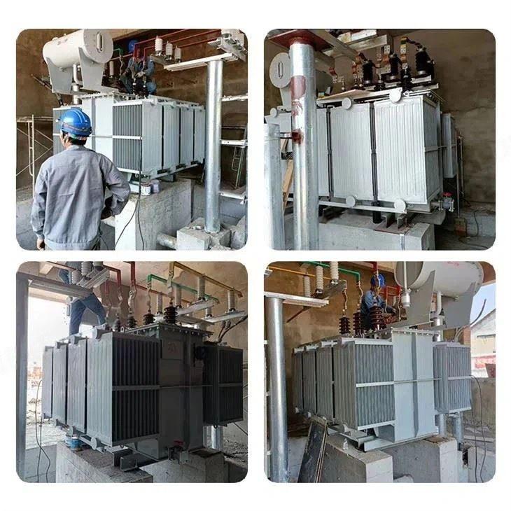
Product Real Shot


Features of oil transformer
1.Stable electrical performance: This product is based on the load of oil-immersed transformers, combined with load characteristics, grid voltage fluctuations and atmospheric overvoltage, to determine a reasonable and reliable insulation level and insulation model, so as to fully ensure the reliable and stable electrical performance of the product. Product environmental safety factor ≥ 1.67.
2. High dynamic stability: The product winding has high mechanical strength and strong burst resistance, which can meet the extreme harsh load environment. In the design and manufacturing process, the dynamic instability sources caused by transformer leakage or possible abnormal transportation are eliminated. The product has high dynamic stability. High impedance, 30% higher than that of power transformers of the same capacity, thus suppressing di/dt and effectively protecting rectifier components.
3. Good thermal stability: advanced product design, strict control of the temperature rise of the heating part of the product and *** hot spot, and leave enough temperature rise margin. If necessary, axial oil channel can be added in the coil, according to the coil load loss value to choose the cooling method, reasonable distribution of oil flow, to achieve *** good cooling effect. The main temperature rise index is at least 5℃ lower than the national standard. Coils and leads are made of copper conductors, with low current density.
4. Strong overload capacity: The product has strong overload capacity and overvoltage capacity, and can operate safely under rated load for a long time, and under 110% overvoltage (ambient temperature 40℃), it can operate safely under full load for a long time. Considering from the aspects of temperature rise, insulation performance and accessories selection, the product design and manufacturing should fully consider the load characteristics to meet the overload requirements.
5. Oil-immersed transformer low-voltage winding in addition to small capacity using copper wire, generally using copper foil winding cylindrical structure; high-voltage winding using multi-layer cylindrical structure, winding amp-turn distribution balance, small magnetic leakage, high mechanical strength, strong short-circuit resistance.
6. The core and winding take fastening measures respectively. Device height, low-voltage leads and other fasteners are equipped with self-locking locking nuts. Adopt the structure of not hanging core, can withstand transportation bumps.
7. Coil and core vacuum drying, transformer oil vacuum filtration filling, will transformer internal moisture reduction.
8. The oil tank adopts corrugated plate with breathing function to compensate the oil volume change caused by temperature change. Therefore, this product has no oil storage cabinet, which obviously reduces the height of the transformer.
9. As the corrugated plate replaces the oil storage cabinet, the transformer oil is isolated from the outside, which effectively prevents oxygen and water from entering and causing the insulation performance to drop.
10.According to the performance of the above 10 points, the oil-immersed transformer does not need to change oil during normal operation, which greatly reduces the maintenance cost of the transformer and extends the service life of the transformer.
Normal operation of the transformer oil storage cabinet oil level should be in about one-half more appropriate.
The air on the oil surface of the oil storage cabinet is connected to the external atmosphere by a ventilation pipe. Ventilation pipe placed in the desiccant, in order to reduce the moisture in the air into the oil storage cabinet. The bottom of the oil storage cabinet is equipped with a sedimentation device to sink the water and dirt invaded into the oil storage cabinet and periodically remove it. At one end of the oil storage cabinet is also equipped with an oil level meter to observe the oil level, when the oil is insufficient due to leakage and other reasons, it should be supplemented by timely oil injection.
Thank you for your attention on Vouchivan ELECTRIC!
We offer Oil immersed transformers, Dry type transformers, Compact transformer substations, etc.Vouchivan Updated
-
Sep 20,2024
How should I choose between an oil-immersed transformer and a dry-type transformer? -
Sep 20,2024
What are the common outdoor substation technologies? -
Sep 20,2024
Causes and Considerations for Oil Leakage and Operating Temperature in Oil-Immersed Transformers


